SHIP MODEL DESIGN & ENGINEERING
Cara Mengubah Gambar GA Menjadi Model Kapal Berskala Akurat: Panduan Teknis
General arrangement (GA) drawings are a key source of information when developing a custom scale ship model. They describe the vessel's principal layout and help establish the relationship between its hull, decks, superstructure and major equipment.
But an accurate physical model is not created simply by shrinking a drawing. The information must be interpreted across different views, converted into a suitable scale, checked for missing details and translated into manufacturable components.
This technical guide explains the main stages, from reviewing engineering references to final model inspection.
1. What Is a GA Drawing in Ship Model Manufacturing?
A general arrangement drawing presents the overall arrangement of a vessel. Depending on the drawing set, it can show deck layouts, accommodation, bridge location, machinery spaces, cargo areas, access routes and major equipment.
For model development, GA drawings help establish the vessel's proportions and the relative positions of important structures. They are particularly useful when creating vessel-specific models for shipyards, shipowners, marine engineering companies and professional exhibitions.
For a drawing-based project, begin with our Build From Drawings service, which explains the reference materials that can support custom model development.
General Arrangement Plan
Establishes the main layout, deck levels, bridge location and major vessel spaces.
Side Profile and Elevations
Helps determine the hull silhouette, deck heights, bow and stern profiles and superstructure position.
Denah Dek
Provide additional information about equipment positions, working areas, hatches and access arrangements.
Gambar Peralatan
Help clarify specialist machinery, cranes, davits, masts and other components that require additional detail.
2. Check the Drawing Views for Consistency
One drawing rarely describes every visible feature in sufficient detail. A side elevation may establish height and length relationships, while a deck plan shows the relative position of equipment. Both views must be interpreted together.
Before design begins, identify the principal dimensions, confirm the drawing revision and list any missing information that could affect the model.
- Check the vessel length, beam and other available principal dimensions.
- Compare bridge and accommodation positions across the available views.
- Review deck levels and the relationships between major structures.
- Identify specialist equipment that needs a separate drawing.
- Record unresolved details that require photographs or customer confirmation.
If only a GA drawing is available, the project may still be feasible. The appropriate level of detail depends on the drawing quality, vessel type, model scale and intended presentation. Read more about the limitations and advantages of building custom ship models from drawings.
3. Convert Full-Size Dimensions into Model Scale
Scale conversion is one of the fundamental calculations in model planning. A scale of 1:200 means that one unit on the model represents 200 of the same units on the real vessel.
Model Dimension = Full-Size Dimension ÷ Scale Denominator
Example: 200 metres ÷ 200 = 1 metre
| Original Vessel Length | Skala | Perkiraan Panjang Model |
|---|---|---|
| 200 m | 1:100 | 200 cm |
| 200 m | 1:200 | 100 cm |
| 200 m | 1:300 | 66,7 cm |
| 200 m | 1:500 | 40 cm |
These examples exclude the display base and case. Before finalizing the scale, consider the model's total display footprint, the visibility of small components and the purpose of the finished model.
Our Panduan Skala Model Kapal explains additional factors involved in choosing an appropriate scale.
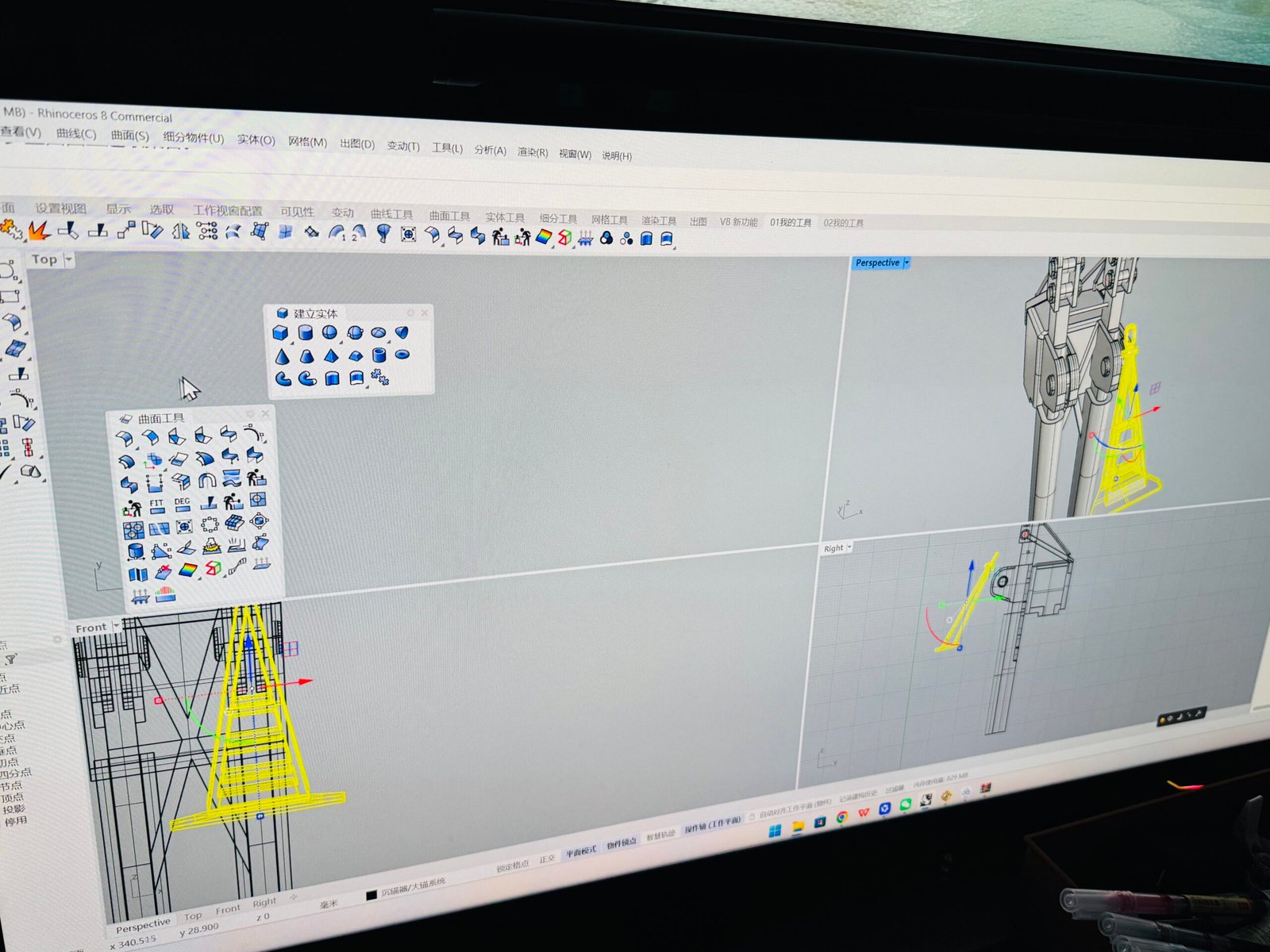
4. Use CAD and 3D Design to Interpret Complex Geometry
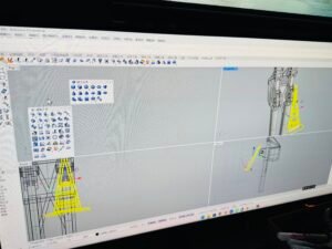
Once the reference information has been reviewed, CAD and 3D design tools can help translate two-dimensional drawings into a three-dimensional representation of the vessel.
This stage may involve developing the hull geometry, defining deck levels, positioning the superstructure and planning individual equipment components. Digital design also provides a way to review proportions before physical fabrication begins.
However, receiving a 3D file does not automatically guarantee accuracy. Its geometry, dimensions, completeness and relationship to the approved vessel configuration must still be checked.
Hull and Main Structures
Develop the main geometry and establish the relationships between the hull, decks and superstructure.
Perencanaan Komponen
Separate complex structures into manageable components for production and assembly.
Dimensional Checks
Compare key measurements and positions with the available engineering references.
Manufacturing Preparation
Determine which parts are suitable for 3D printing, CNC processing or other fabrication methods.
Pelajari lebih lanjut tentang CAD & 3D Design for custom ship models and how digital references can support detailed model planning.
5. Decide Which Details Can Be Reproduced at Scale
A full-size vessel contains components that become extremely small when converted into a scale model. Some parts may need to be simplified or adapted so they remain visible, structurally sound and suitable for display.
The objective is to preserve the vessel's recognizable features and important geometry while selecting practical methods for individual details.
- Hull geometry: retain the vessel's defining proportions and silhouette.
- Superstructure: preserve deck levels, bridge configuration and accommodation shapes.
- Deck equipment: reproduce the position and recognizable form of major machinery.
- Small fittings: plan railings, ladders, masts and piping according to the scale.
- Vessel identity: include the correct name, markings, logo and color references where specified.
Detail selection should be planned before fabrication, particularly for offshore vessels, workboats and specialist ships with complex working decks.
6. Select Appropriate Manufacturing Methods
After the design has been checked, the model can move into production. The appropriate methods depend on the size and shape of the components, the material, the intended finish and the quantity required.
Pembuatan Lambung Kapal
Develop the main hull structure according to the approved dimensions and geometry.
3D Printing and CNC
Use suitable digital fabrication methods for selected structures and detailed components.
Assembly
Bring together the hull, superstructure, decks and separately manufactured components.
Pengecatan dan Penyelesaian
Apply the required colors, markings and surface finish, then install final details.
For an overview of how these activities fit together, visit the Scales Model Production Process halaman.
7. Verify the Finished Model Against the Engineering References
Final inspection should compare the physical model with the approved drawing package rather than rely only on visual impression.
- Check the principal dimensions and overall proportions.
- Compare hull geometry and superstructure locations with the source drawings.
- Review the placement of major equipment and deck structures.
- Confirm the requested colors, markings and vessel identification.
- Inspect assembly quality, surface finish and fragile components.
For projects that will be displayed at shipyards, offices, museums or exhibitions, packaging and handling requirements should also be considered before shipment.
8. Prepare the Information Needed to Start a Project
A useful project brief does not need to be complicated. The goal is to give the model manufacturer enough information to understand the vessel, the required result and any technical constraints.
Referensi Teknis
- GA drawing and side profile
- Deck plans and equipment drawings
- CAD files, if available
- Vessel name and principal dimensions
- Photographs and color references
Project Requirements
- Desired scale or model length
- Jumlah yang dibutuhkan
- Tujuan penggunaan dan lokasi pemasangan
- Branding and identification details
- Delivery destination and target date
Where some information is missing, the manufacturer can review the available references and identify what is needed before finalizing the design scope.
Have GA Drawings for a Custom Ship Model?
Scales Model develops vessel-specific physical models from general arrangement drawings, technical plans, photographs and suitable CAD references. Share your available files, target scale and project requirements to discuss the next steps.
Send Drawings & Request a Quote Jelajahi Model Kapal KustomPertanyaan yang Sering Diajukan
Can a ship model be made from a GA drawing alone?
A GA drawing can provide the starting point for model development. Whether it is sufficient for the required detail depends on the vessel's complexity, drawing quality, chosen scale and intended use. Additional references may be needed for detailed components.
Which drawing formats can be used for ship model design?
Depending on the project, useful references can include PDF drawings, DWG files, vessel profiles, deck plans, equipment drawings and suitable digital engineering files. The available files should be reviewed before production planning.
Does a 3D file always produce a more accurate model?
No. A 3D file can help with geometry and component planning, but its accuracy depends on the data quality, completeness and correspondence with the actual vessel. Dimensions and important details should be checked against reliable references.
How do I calculate the length of a scale ship model?
Divide the vessel's full-size length by the scale denominator. For example, a 200-metre vessel at 1:200 scale has an approximate model length of 1 metre, excluding the base and case.
What if I do not know which scale to choose?
Provide the vessel's dimensions, intended display space, required level of detail and application. These factors can be reviewed together to recommend a practical scale.
 Indonesian
 English
 Chinese
 Spanish
 German
 French
 Korean
 Japanese